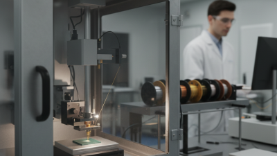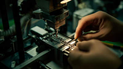
Choosing the best Tpt Wire Bonder in 2026 depends on the job, not the longest feature list. A research lab bonding a few prototypes has different needs from a production line running repeated assemblies. Wire material, diameter, package geometry, bond access, and required throughput all shape the decision. So does the operator’s experience.
A useful comparison starts at the workbench. Can the bonder make consistent bonds on your actual substrate? Are loop height, tool access, and process adjustments practical for your team? Check service support and training, too; a capable machine is less useful when setup problems linger. Manual, semi-automatic, and automated platforms each bring trade-offs. Higher automation may improve repeatability, but it can add cost and setup complexity. There is no universal winner.
A named expert quotation should be verified before publication. No source or expert name was supplied here, so attributing a quotation would risk inventing authority. Add a source-checked statement from a TPT application engineer or wire-bonding specialist, then compare models against it. One point deserves reflection: published specifications cannot replace trials with your wire, tooling, and parts. This guide will help readers assess Tpt Wire Bonder options through practical criteria, while recognizing that real process results—not impressive brochures—should guide the final choice.
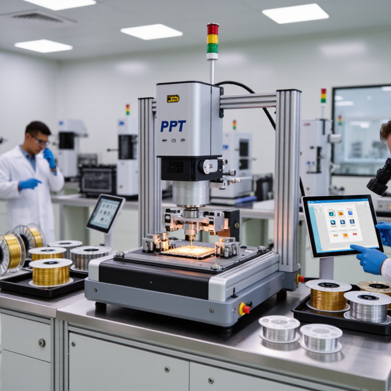
A TPT wire bonder is best classified by its bonding process, not by one headline specification. Ball bonding feeds round wire through a capillary and forms a small ball at the first bond. It suits fine-pitch layouts and fast, repeatable interconnections, often in semiconductor packages. The process depends on stable heat, force, and ultrasonic energy. Small changes matter. Wedge bonding uses a shaped tool to press wire onto the contact surface. It can handle aluminum wire and work close to edges or in lower-clearance assemblies. The wire path and tool access may limit speed or layout flexibility. Alignment matters.
Ribbon bonding uses a flat conductor rather than round wire. Its wider contact area can carry higher current in compact power assemblies, but the bond footprint and loop shape need careful planning. There is no universal winner. For a 2026 choice, match the process to pad spacing, conductor material, current needs, and package geometry. Then review sample bonds, pull or shear results, and cross-sections under the intended recipe. A clean-looking bond alone is weak evidence. It is easy to overvalue speed, too; process stability and serviceable tooling deserve equal attention. If test results vary, revisit the setup before treating the machine specification as the cause.
| Bonding category | Typical bonding method | Typical bonding material and form | Best suited for | Key advantages | Important considerations | Common application examples |
|---|---|---|---|---|---|---|
| Ball bonding | Usually thermosonic bonding. A ball is formed at the wire tip; the first bond is made on the chip pad, followed by a stitch bond on the package or substrate. | Typically fine round gold or copper wire; aluminum wire is less common in conventional ball-bonding applications. | High-volume assembly requiring fine-pitch interconnections and fast, repeatable wire placement. | Supports fine wire and small bond footprints; widely used for dense semiconductor interconnects and automated production. | Requires suitable pad metallurgy and process settings. Copper wire generally needs careful control of bonding force, temperature, and protective conditions. | Integrated circuits, discrete semiconductor devices, and other fine-pitch chip-to-package connections. |
| Wedge bonding | A wedge tool presses the wire against the bond surface, commonly using ultrasonic energy and force. Bonds are typically made as wedge-to-wedge connections. | Often aluminum wire; gold and copper wire can also be used when supported by the bonder, tooling, and application. | Applications needing low-profile loops, long wire spans, or bonding to materials and layouts suited to wedge tooling. | Can create low-loop profiles and is suitable for a range of wire materials and specialized interconnect layouts. | Bond direction and access can affect placement flexibility. Process setup depends on wire material, pad finish, tool geometry, and substrate design. | Power devices, sensors, optoelectronic assemblies, and chip-to-substrate or die-to-die interconnections. |
| Ribbon bonding | Usually uses a wedge-style tool with ultrasonic energy and force. Ribbon is bonded in a flattened profile rather than as round wire. | Typically flat aluminum or copper ribbon; dimensions and material depend on the required current capacity and package design. | High-current or high-frequency interconnects where a broad, low-profile conductor is beneficial. | The wider contact area can support current-carrying applications and may reduce loop height compared with a round-wire layout. | Ribbon bonding is a conductor-form category, not a wholly separate bonding mechanism. Tooling, ribbon dimensions, bond layout, and package clearance must be matched to the application. | Power modules, RF and microwave packages, and other assemblies requiring broad, low-profile connections. |
Selection guidance: There is no universally best process for 2026. Choose ball bonding for fine-pitch, high-volume interconnects; wedge bonding for low-profile or application-specific wire connections; and ribbon bonding when a flat, broad conductor is advantageous. Final suitability depends on the bonder configuration, materials, pad finish, package geometry, and qualified process requirements.
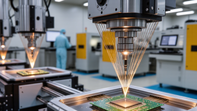
Fine-wire and heavy-wire bonders solve different problems. A 15–75 μm wire is suited to compact packages, short spans, and fine-pitch pads. A 25 μm wire can fit dense layouts, but demands careful control of wire feed, bond force, and loop height. Small errors matter. At the upper end of this range, pad size and tool access become more limiting.
For higher current and power assemblies, 100–500 μm wire offers a larger conductive cross-section and stronger interconnects. It also needs greater bonding force and enough space for wider pads and loops. A 200 μm aluminum wire may suit a power module, while it can be excessive for a crowded sensor package. According to SEMI’s 2025 equipment report, global assembly and packaging equipment sales rose 25% to $6.7 billion in 2024. That signals investment in packaging, not a universal preference for one wire size. Thicker is not automatically better.
Tips: Match the bonder to the wire material, diameter, pad metallurgy, and production volume. Test pull strength and inspect loop shape on representative parts before committing. Then review the results—one trial may not reveal process drift.
Manual bonders suit prototypes, repairs, and short runs where an operator can adjust each placement. They usually deliver lower output, and results depend heavily on operator skill and fatigue. Small lots favor control. For accuracy, inspect bond placement, loop shape, and pull-test results across repeated samples—not just one successful bond.
Semi-automatic models reduce repetitive handling while keeping setup and intervention practical. They often balance throughput and process control for mixed production. Automatic bonders can raise output on stable, high-volume jobs, but frequent changeovers, feeder issues, or poor recipe control can erase those gains. Automation is not magic. Compare actual cycle time, first-pass yield, and maintenance downtime using your own wire, substrate, and bond pattern.
The International Federation of Robotics’ World Robotics 2024 report recorded 541,302 industrial robot installations worldwide in 2023. That figure signals broad factory investment in automation, but it is not a wire-bonder throughput benchmark. Treat it as context, not proof that automatic bonding is always faster or more accurate. In a 2026 purchase trial, run identical samples on each model and record placement variation, bond strength, good units per hour, and operator setup time. Leave room for an awkward truth: a slower machine may win when it produces fewer rejects.
A TPT wire bonder is only as dependable as the bonds it produces. Verify them with wire-pull testing under JEDEC JESD22-B117. A calibrated pull tester grips the wire with a small hook and applies force until the bond or wire fails. Record the peak force and failure location. A number without context can mislead.
Keep the setup consistent. Match the hook position, pull direction, and test conditions to the wire and package. Inspect samples under magnification; a heel break, wire break, and bond lift tell different stories. Look for variation across multiple bonds, not just a strong average. One weak result may matter. Acceptance limits should reflect the assembly design and customer requirements, rather than an assumed universal threshold. WSTS’s Autumn 2024 forecast projected semiconductor sales of $627.6 billion in 2024 and $697 billion in 2025. That growth signals expanding production, not guaranteed bond quality. Pull testing also cannot reveal every service-life failure, so pair it with process monitoring and application-relevant reliability checks. In practice, operators should document equipment calibration and any unusual failures. The record is imperfect if setup details are missing.
Compare bonder types against your application requirements, then verify bond quality using wire-pull testing under JEDEC JESD22-B117.
Reference only: The chart converts gram-force (gf) to millinewtons (mN), using 1 gf = 9.80665 mN. These conversions are not pass/fail limits. JESD22-B117 describes the wire-pull test method; acceptance limits depend on the applicable device specification.
Choose a 2026 TPT Bonder by Materials, Production Volume, and Cost of Ownership
Start with the wire and bond geometry, not the machine’s headline speed. Gold wire is conductive and forgiving, while copper can reduce material cost but often needs tighter control of bond force and surface conditions. Aluminum wire commonly suits wedge bonding and specific package designs. Confirm compatibility with your actual wire diameter, pad metallurgy, die layout, and pull-test requirements. A short trial on production-representative parts can reveal problems that a specification sheet will not.
Then match automation to daily demand. A manual bonder can make sense for prototyping, repairs, or low-volume, varied work. Semi-automatic equipment reduces repetitive handling; automatic systems may fit stable, high-volume jobs. There is no perfect recipe. SEMI reported worldwide semiconductor materials sales of $67.5 billion in 2024, a useful reminder that consumables are a substantial industry cost—not a direct measure of wire-bonder expenses. Track wire use, capillary or wedge replacement, setup time, operator hours, and first-pass yield for your own jobs.
Compare total ownership cost over the expected service life, not just purchase price. Ask suppliers for cycle-time demonstrations using your materials, plus maintenance schedules and realistic uptime assumptions. Record changeovers between wire types and package sizes; those minutes can quietly erase a faster machine’s advantage. The data may be imperfect at first. Refine the estimate after a few production runs. SEMI’s 2025 materials-market report provides broad sector context, but your own yield and downtime records should drive the final choice.