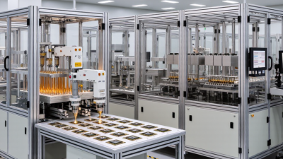
Why Choose a Wire Bonding Machine?
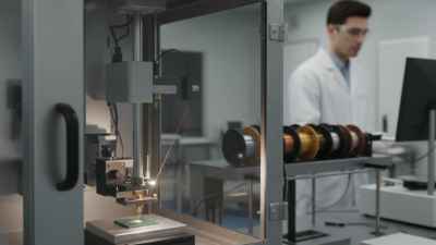
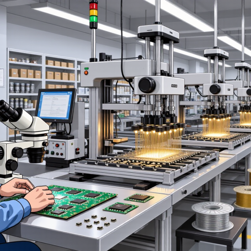
Choosing a Wire Bonding Machine is a production decision, not simply a purchase based on advertised speed. The right system must suit the package, wire material, pad layout, and expected output. Details matter. On a factory floor, an operator may inspect a bond under magnification, checking loop shape, placement, and tool wear. A machine suited to fine-pitch packages may be unnecessary for a low-volume line, while an undersized system can limit future work. Fit comes first.
A sound evaluation looks beyond cycle time. Compare bonding accuracy, repeatability, supported wire types, recipe controls, maintenance needs, and operator training. Ask how the machine handles your actual parts, not just a demonstration sample. A short trial using representative substrates can reveal setup challenges that a specification sheet may not show. It is tempting to favor the fastest model. Yet stable bonds, practical changeovers, and accessible service often matter more in daily production. No machine removes every process variable; materials, tooling, and operator settings still require careful control. That caveat is worth remembering. This guide explains the main reasons manufacturers choose a Wire Bonding Machine, which features deserve attention, and how to judge whether a system fits a specific application. The best choice is rarely the most impressive brochure. It is the one that performs reliably under real working conditions.
What a Wire Bonding Machine Does
A wire bonding machine connects a semiconductor die to a package or circuit substrate using very thin metal wire. It positions the wire, forms a small bond at each contact, then creates a controlled loop between them. The connections carry electrical signals and power. In practice, the wire can be finer than a human hair. Small movements matter.
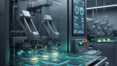
The machine typically uses a bonding tool, a heated work area, and carefully timed pressure or ultrasonic energy. Depending on the process, it may form a ball bond or a wedge bond. A camera helps locate tiny pads, while motion controls guide the tool from one point to the next. The operator sets parameters such as bond force, temperature, and loop height. Too much force can damage a pad; too little may leave a weak connection. There is no single recipe for every assembly.
After bonding, technicians inspect the wire shape and bond locations, sometimes using magnification or pull testing. They look for lifted bonds, inconsistent loops, and wires that touch nearby features. A stable setup helps, but it does not eliminate variation. Even a good recipe may need adjustment when materials or pad layouts change. That part can be frustrating. Small details decide a lot.
How Wire Bonding Creates Electrical Connections
A wire bonding machine forms a direct electrical path between a semiconductor die and its package. It places a thin metal wire between a tiny bond pad and a lead or substrate contact. The connection is small, but each bond must hold firmly and conduct reliably.
Depending on the process, the machine uses heat, ultrasonic vibration, pressure, or a combination of these. A capillary guides the wire into a controlled loop, then presses it onto the first contact and the second. Gold, copper, and aluminum wires are common choices, though the suitable material depends on the device and assembly requirements. Precise alignment matters. A shift of only a few micrometers can weaken a bond or cause a short.
Operators check parameters such as bond force, temperature, ultrasonic energy, and loop height. Pull and shear tests can reveal weak connections that are hard to spot under ordinary lighting. Small details matter. Even so, a proven recipe may need adjustment when wire diameter, pad finish, or package geometry changes. Machines improve repeatability, but they do not remove the need for careful setup and inspection.
Why Choose a Wire Bonding Machine?
A wire bonding machine forms fine metal-wire connections between a semiconductor die and its package or substrate. Shorter, thinner interconnects can help reduce electrical resistance.
How to read this chart: These are calculated DC resistances for straight, 25 µm diameter wires using nominal bulk-metal resistivities at 20°C: gold 2.44 × 10⁻⁸ Ω·m, copper 1.68 × 10⁻⁸ Ω·m, and aluminum 2.82 × 10⁻⁸ Ω·m. Values exclude bond-interface resistance; actual connections vary with wire material, geometry, temperature, and bonding quality.
Key Advantages of Wire Bonding Machines
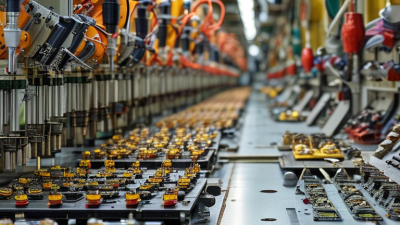
Wire bonding machines form electrical connections by joining fine metal wire to a chip’s bond pads and package leads. Their controlled movement helps place each bond accurately, even when pads are closely spaced. In production, that repeatability can reduce variation between devices.
Small details matter.
A key advantage is process flexibility. Operators can adjust bonding paths and parameters for different package layouts, wire types, and production needs. This makes the equipment useful for both established designs and changing product runs. The method also requires relatively little space compared with some interconnection approaches. Less floor space can simplify line planning.
Wire bonding can support efficient throughput, but speed depends on the device, recipe, and inspection requirements. A poorly tuned setup may produce weak bonds or damage delicate pads, so monitoring pull strength, bond shape, and tool condition is important. Setup can be fussy. Regular calibration and operator training help keep results consistent, though they cannot remove every source of variation. A practical assessment should include the full process, not just the machine’s rated speed.
Industries and Applications That Use Wire Bonding
Wire bonding machines connect silicon dies to package leads with fine gold, copper, or aluminum wires. Their work appears in power modules, sensors, memory, telecom components, and control electronics. The process suits compact packages and high-volume production, especially where inspectable connections matter. WSTS reported global semiconductor sales of $627.6 billion for 2024 in its Spring 2025 report. That figure signals broad chip demand, not wire-bonding market share. The distinction matters.
Automotive electronics are a clear use case. Bonded power devices and sensor packages may face vibration, heat, and tight space limits. OICA counted 93.5 million motor vehicles produced worldwide in 2023, illustrating the scale of electronics-intensive vehicle manufacturing. Wire bonding also supports consumer devices, industrial controls, and medical instruments, where small connections must endure handling and operation. Yet it is not ideal for every package; fine-pitch layouts or demanding electrical paths may call for another interconnect method. Not every design fits. Engineers should compare loop height, wire material, bond strength, throughput, and inspection results using the actual package. A fast machine cannot rescue a poor process window.
Factors to Consider When Choosing a Wire Bonding Machine
Why Choose a Wire Bonding Machine?
Factors to Consider When Choosing a Wire Bonding Machine
When choosing a wire bonding machine, start with the package types and wire materials used in daily production. A setup for fine-pitch sensor packages may not suit larger power devices. Check the supported wire diameter, bonding area, loop height, and tool access against real parts, not just sample specifications.
Small mismatches matter.
Then assess placement accuracy, bond consistency, and cycle time together. A fast machine is not useful if operators must stop often to correct weak bonds or misplaced loops. Ask for trial runs using your substrate, die, and production recipe. Inspect pull-test results and bond appearance across repeated runs. Look closely.
Also consider changeover time, operator training, maintenance access, and data records. If the product mix changes weekly, recipe management may matter more than peak throughput. Confirm spare-part availability and service response expectations before purchase. A polished demonstration rarely shows the awkward setup at shift change. Leave room for doubt: one trial cannot predict every factory condition. Compare measured results, operating costs, and the skills available on your floor. The right machine should suit current output and likely process changes without creating constant workarounds.