


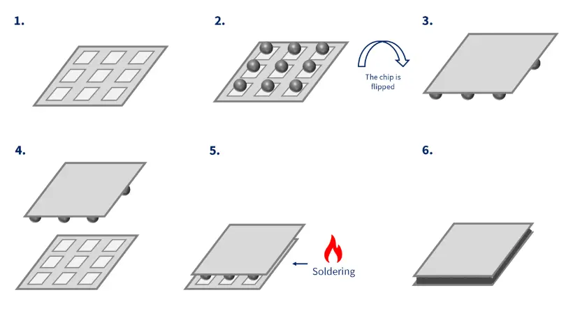
Die bonding: The process of placing a chip onto a substrate.
1. Development of Bonding Methods
To ensure that semiconductor chips operate normally in various fields, external bias voltage and input must be provided. Therefore, it is necessary to connect metal leads to the chip pads. In the early days, metal leads were connected to chip pads through soldering. Since 1965, this connection method has evolved from wire bonding to flip chip bonding, and then to through-silicon vias (TSV), experiencing various development stages.
As the name suggests, wire bonding is a method that uses metal wires for connections. Flip chip bonding replaces metal wires with bumps, increasing the flexibility of the lead connections. TSV, as a completely new method, connects the upper and lower chips to the printed circuit board (PCB) through hundreds of vias.
2. Comparison of Bonding Methods: Wire Bonding and Flip Chip Bonding
The decision between wire bonding and flip-chip technology in semiconductor packaging is not straightforward. Engineers need to take into account factors such as cost, performance, and the specific application.
Wire bonding is the most cost-effective and widely used semiconductor packaging method, accounting for 90% of integrated circuits globally.
On the other hand, flip-chip technology provides shorter interconnection lengths and enables vertical stacking of chips, but it involves a more complex manufacturing process.
Chip bonding, as the after step in the cutting process, is a technique for securing the chip to the substrate. Wire bonding, as a subsequent step in chip bonding, ensures the transmission of electrical signals. Another connection method similar to wire bonding is flip chip bonding (see "Chip Bonding: The Process of Assembling a Chip on a Package Substrate"), where both methods use very small metallic objects to connect the pads on the chip to the pads on the PCB (in the case of wire bonding, this is only applicable under the lead frame).
In comparison, wire bonding, which utilizes metal wires for connections, has several disadvantages: the metal wires are longer and have a smaller diameter than bumps, resulting in longer signal transmission times. Additionally, due to the high impedance of the metal wires, signals are prone to distortion. Furthermore, the solder neck is susceptible to breaking, and its bonding strength is relatively weak, leading to poor tensile strength.
On the other hand, while the operation of connecting small solder balls in flip chip bonding can be somewhat complex, it offers many advantages in terms of connection reliability and electrical signal transmission.
3. What is Wire Bonding?
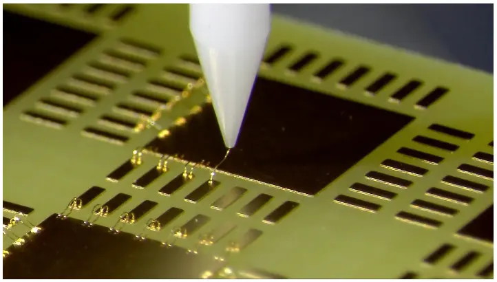
Wire bonding is a method of connecting metal wires to pads, serving as a technology to link internal and external chips. Structurally, the metal wire acts as a bridge between the chip's pads (first bond) and the carrier pads (second bond). In the early days, lead frames were used as carrier substrates, but with the rapid advancement of technology, PCBs are increasingly being used as substrates. The wire bonding that connects two independent pads varies significantly in terms of wire material, bonding conditions, bonding locations (which may connect not only the chip and substrate but also two chips or two substrates), and other factors.
4. Wire Bonding: Thermo-Compression, Ultrasonic, and Thermosonic Methods
There are three main methods for connecting metal wires to pads: the thermo-compression method, the ultrasonic method, and the thermosonic method.
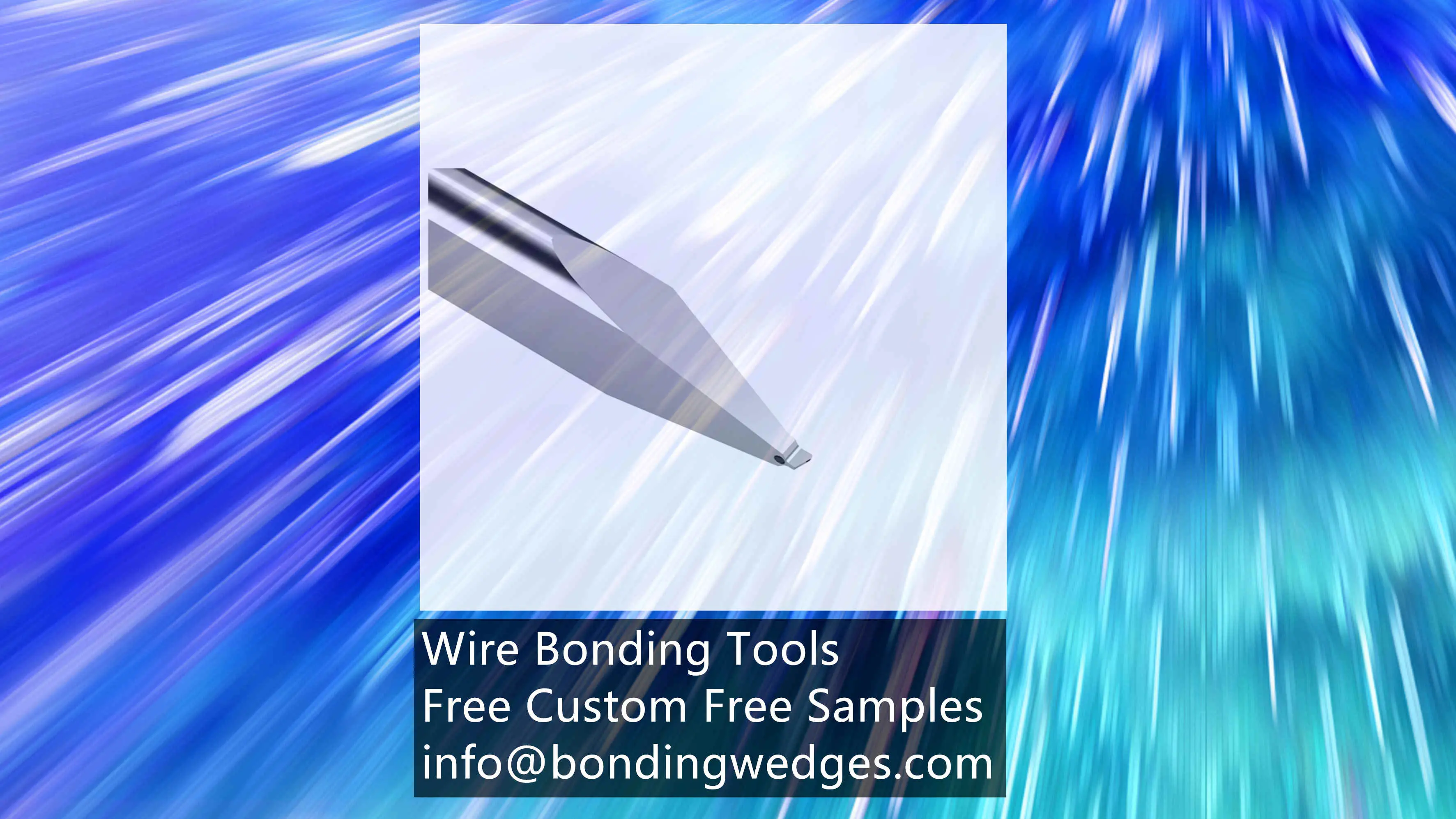
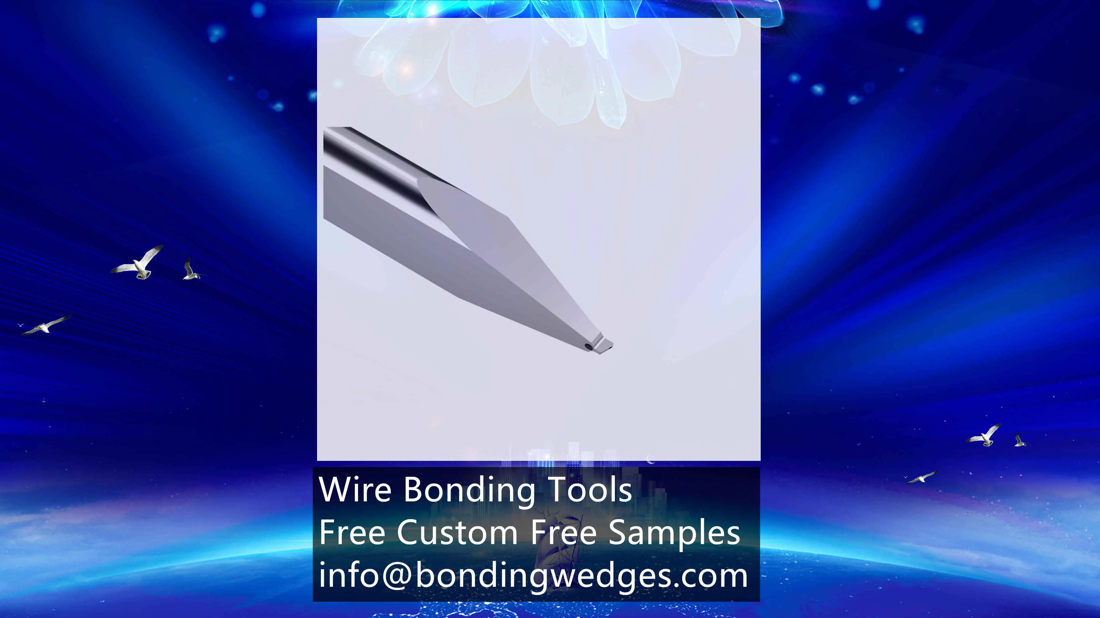
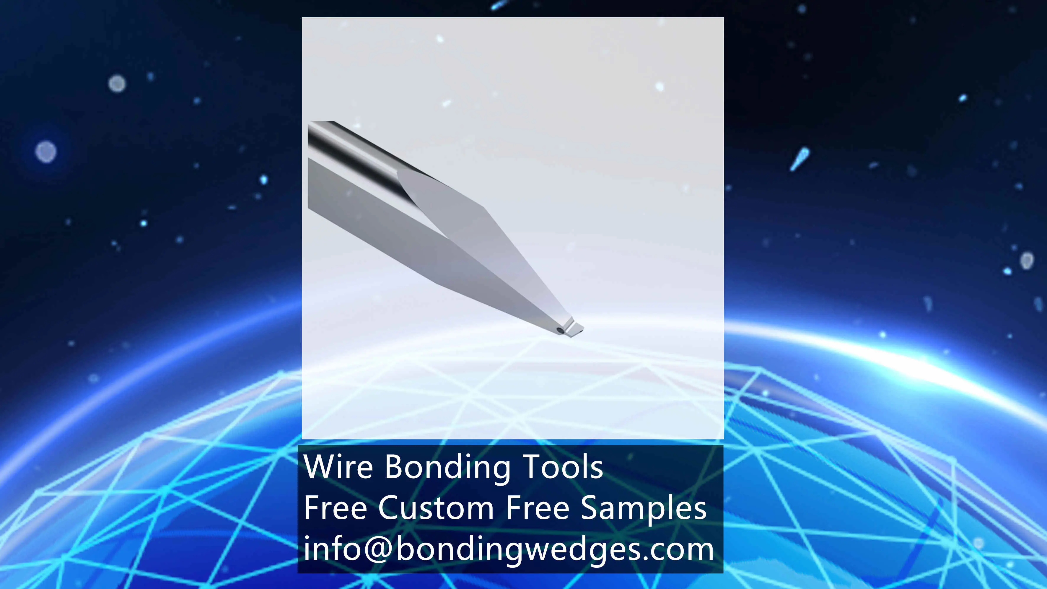
1. **Thermo-Compression Method**: This method connects the pad and the capillary wedge (a tool for moving metal wires that resembles a capillary tube) through heating and compression. The temperature of the chip pad is preheated to around 200°C, and then the temperature at the tip of the capillary wedge is increased to form a ball shape. Pressure is applied through the capillary wedge to connect the metal wire to the pad.
2. **Ultrasonic Method**: In this method, ultrasonic waves are applied to a wedge tool (similar to the capillary wedge but does not form a ball shape) to achieve the connection between the metal wire and the pad. The advantage of this method is its low processing and material costs. However, because it replaces the heating and pressurizing processes with easily operable ultrasonic waves, the bonded tensile strength (the ability to withstand pulling forces on the wire after bonding) is relatively weak.
3. **Thermosonic Method**: This is the most commonly used method in semiconductor processes. It combines the advantages of both the thermo-compression and ultrasonic methods. The thermosonic method applies heat, pressure, and ultrasonic waves to the capillary wedge, allowing for optimal connections. In the backend processes of semiconductors, bonding strength is more critical than cost. Therefore, despite the higher cost of this method, thermosonic wire bonding is the most frequently adopted bonding technique.
### 5. Materials for Bonding Metal Wires: Gold (Au), Aluminum (Al), and Copper (Cu)
The choice of material for metal wires is determined by a comprehensive consideration of various welding parameters, which are combined to form the most appropriate method. These parameters include the type of semiconductor product, packaging type, pad size, wire diameter, welding method, and reliability indicators such as tensile strength and elongation of the metal wire. Typical materials for metal wires include gold (Au), aluminum (Al), and copper (Cu), with gold wires being commonly used in semiconductor packaging.
Gold wire has excellent conductivity, is chemically stable, and has strong corrosion resistance. However, the main drawback of aluminum wire, which was widely used in the past, is its susceptibility to corrosion. Gold wire also has high hardness, allowing it to form a good ball shape during the first bond and to create a well-defined semicircular wire loop during the second bond.
Aluminum wire has a larger diameter and pitch compared to gold wire. While high-purity gold wire can form wire loops without breaking, pure aluminum wire is prone to breakage, so it is often alloyed with elements like silicon or magnesium for improved performance. Aluminum wire is primarily used in high-temperature packaging (such as hermetic sealing) or in ultrasonic methods where gold wire cannot be used.
Copper wire, although cheaper, has a very high hardness. If the hardness is too high, it becomes difficult to form a ball shape, and there are many limitations when forming wire loops. Additionally, during the ball bonding process, pressure must be applied to the chip pad; excessive hardness can lead to cracks in the thin film at the bottom of the pad. There is also the risk of the bonded pad layer experiencing "peeling." Despite these issues, copper wire is increasingly favored because the metal interconnects in chips are made of copper. To mitigate the drawbacks of copper wire, it is often alloyed with small amounts of other materials.
### 6. Different Materials, Different Wire Bonding Methods: Gold Wire vs. Aluminum Wire
In wire bonding, the capillary wedge is arguably the most critical tool. Typically, gold wire is used with capillary wedges, while aluminum wire is used with wedge bonding. The capillary wedge achieves bonding by forming a ball shape, whereas wedge bonding does not require this.
If gold wire employs the "thermosonic-capillary wedge-ball" bonding method, aluminum wire uses the aluminum wedge wire bonding method, which follows the "ultrasonic-wedge bonding" approach. Due to its lower tensile strength, the aluminum ultrasonic method can only be used in special circumstances, while over 90% of cases utilize the "gold wire-thermosonic method." However, the thermosonic method also has its drawbacks, such as the fragility of the ball neck. Therefore, careful management of the Heat Affected Zone (HAZ)—the area where the metal wire material is slightly melted by the high temperature of the capillary and then recrystallizes during solidification—is essential.
Contact Us
For any questions regarding our products or solutions, kindly entrust them to us and we will respond within 24 hours.
KeyWords
Wedge Bonding ToolWedge Tool
Bonding Wedge
Au Wire Bonding
Concave wedge Tool
Wedge Bonding Machines
Wire Bonding ToolsBonding Equipment SuppliersFine Pitch Bonding ToolsWedge BonderWire bonding equipmentSemiconductor bonding toolsPrecision bonding toolsHigh-performance wire bonding toolsSemiconductor industry toolsBonding tool manufacturerCustomizable wire bonding solutionsQuality wedge bonding equipment