
Leave Your Message

7 Tips for Choosing Wire and Ribbon Guides for Wire Bonders

Choosing the right Wire Guides and Ribbon Guides for Wire Bonders can determine whether a bonding line runs smoothly or repeatedly stops. These small components guide delicate wire and ribbon through tight paths. Their alignment affects loop shape, placement accuracy, surface wear, and production stability.

George G. Harman, a respected microelectronics packaging authority, writes, “The wire bond is the most common interconnection method in microelectronics.” That connection begins with controlled guidance. A guide with the wrong radius can scrape a fine wire. A rough ceramic surface may create hidden damage before the bond fails inspection. Even a small height mismatch can change ribbon tension.

This guide explains seven practical selection points. It considers material hardness, surface finish, groove geometry, wire diameter, ribbon width, and equipment compatibility. It also examines cleaning, replacement intervals, and supplier consistency. Measure the actual wire path, not only the catalog drawing. That distinction matters.

Experience often reveals what specifications miss. A guide may look correct yet produce unstable loops after several hours. Heat, vibration, contamination, and operator handling can change performance. Do not ignore those details.

There is no universal guide for every wire bonder. That is an uncomfortable truth. Engineers must balance reliability, cost, availability, and process limits. Some recommendations may require adjustment after trials. The best choice is usually validated through samples, microscope checks, and controlled production testing. Small evidence beats confident assumptions.
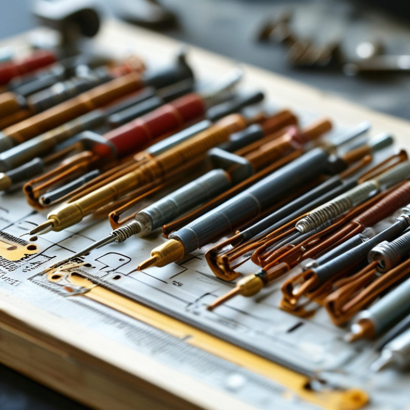
7 Tips for Choosing Wire and Ribbon Guides for Wire Bonders

Understand the Role of Wire and Ribbon Guides in Wire Bonders

Wire and Ribbon Guides in Wire Bonders

Wire and ribbon guides control the material path between the spool, bonding tool, and work surface. Their role is more important than simple positioning. A guide keeps wire centered, limits lateral movement, and supports stable loop formation.

Small alignment errors can create uneven loops, heel cracks, or inconsistent bond placement. I have seen a guide look clean while its contact surface had a fine wear groove. That groove changed wire movement during longer production runs.

Choose the guide according to the wire or ribbon shape, hardness, and required travel speed. A round wire needs a different channel profile from a flat ribbon. The contact area should support the material without squeezing it.

Sharp edges may scrape insulation or deform soft metal. Polished surfaces help, but polishing alone cannot correct poor geometry. Check the guide under magnification, especially near entry and exit points. Keep the inspection record practical. Note scratches, residue, alignment, and replacement intervals.

Guide material also affects heat transfer, contamination, and service life.

Confirm that its dimensions match the bonder setup and bonding tool. Do not assume an interchangeable part will perform equally. That assumption can be expensive.

During setup, observe the wire at low speed before judging production performance. Listen for intermittent rubbing and watch for sudden lateral motion. A simple test pull may reveal resistance that software cannot detect.

I still review guide selection after process changes, because a successful setup can become unsuitable when wire size, tension, or loop geometry changes.


Match Guide Materials with Wire Types and Bonding Conditions

Wire and ribbon guides should be matched to the wire, not selected by shape alone. Gold wire is relatively soft, so a smooth ceramic or sapphire contact surface helps reduce scoring. Copper wire is harder but more sensitive to friction, oxidation, and contamination. Use a highly polished guide with a carefully controlled radius. Aluminum ribbon needs a wider, accurately aligned channel. A narrow throat can twist the ribbon before bonding.

Guide geometry matters as much as material. Check wire diameter, ribbon width, loop height, and feeding angle together. Ruby, sapphire, and fine-grain ceramic can provide stable wear resistance, but their surface finish must be verified under magnification. A guide that looks smooth may still damage copper. Measure the contact path. Small geometry punishes small errors.

Bonding conditions also change the choice. Higher ultrasonic energy and heated workholders can increase guide wear, especially when debris accumulates. Cleaning intervals should be based on actual friction marks, wire breaks, and bond-strength data. SEMI’s 2024 World Fab Forecast projected global fab capacity growth of about 6% in 2024, increasing pressure on stable, repeatable feeding. The WSTS 2024 forecast placed semiconductor sales near 611.2 billion dollars, reinforcing the need to reduce avoidable stoppages. These figures do not select a guide for you. They only show why small guide decisions matter at scale. A practical trial should compare two materials under identical wire tension, temperature, and ultrasonic settings. The first result may be misleading. Recheck after extended production.

Select Guide Dimensions for Accurate Wire and Ribbon Alignment

Choosing wire and ribbon guides starts with alignment, not appearance. A guide must control lateral movement without scraping the conductor. In production trials, I measure the actual wire or ribbon after forming, not only the nominal drawing size. For a 25-micrometer wire, the channel should provide controlled clearance while preventing visible side play. Ribbon guides need more attention. Their width, thickness, edge radius, and entry angle all affect placement accuracy. Sharp edges can mark soft materials. Small errors become larger at long spans.

Yole Group’s 2024 Status of the Advanced Packaging Industry report forecasts advanced packaging revenue to approach 49 billion dollars by 2029. SEMI’s 2024 World Fab Forecast also tracks more than 1,400 fabs and production lines worldwide. These figures reflect rising pressure for repeatable assembly, even when the guide is a small component. Select dimensions from measured process data. Check guide width, groove depth, radius, and mounting height together. A useful starting point is conductor width plus a small, verified side clearance. Do not copy one tolerance across every machine. I have seen a theoretically correct guide create drag after coating buildup. That detail is easy to miss. Recheck alignment under operating temperature, vibration, and real cleaning intervals. The first design may be wrong. That is normal, but ignoring the evidence is not.

Evaluate Surface Quality, Wear Resistance, and Thermal Stability

7 Tips for Choosing Wire and Ribbon Guides for Wire Bonders

Evaluate Surface Quality, Wear Resistance, and Thermal Stability

A guide’s surface directly affects wire tension, loop shape, and bonding consistency. Inspect the contact path under magnification before installation. Look for scratches, burrs, pits, or uneven polishing. Even a tiny defect can drag fine wire and create unstable loops. Measure surface roughness when possible, rather than trusting a polished appearance. Measure, do not guess. I have seen guides pass a visual check but still mark wire during production trials.

Wear resistance matters when guides handle continuous motion, especially with ribbon materials. Compare the guide material’s hardness with the expected contact load and wire type. Check edges after a defined number of bonding cycles. A worn entry radius may produce metal debris or gradually change the wire path. Keep inspection records with cycle counts, wire size, and observed defects. This supports reliable maintenance decisions. However, laboratory wear data may not match your feeder speed or cleaning method.

Thermal stability is equally important near heated workholders or high-temperature processes. Review the guide’s dimensional change across the full operating range. Low expansion helps preserve alignment during repeated heating and cooling. Also examine thermal shock resistance, because sudden temperature changes can cause cracking or distortion. Leave a practical safety margin below the material’s maximum rating. One overlooked detail is mounting stress. A stable guide can still shift if fasteners expand unevenly. Test it after several heat cycles, not only when the assembly is cold.

Verify Compatibility, Maintenance Needs, and Supplier Support

7 Tips for Choosing Wire and Ribbon Guides for Wire Bonders

Wire and ribbon guides should match the bonder’s wire diameter, ribbon width, material, and feed path. Verify the guide’s mounting pattern and working clearance before ordering. A small mismatch can create scraping, unstable loops, or wire breaks. Check guide hardness and surface finish, especially when using fine wire or delicate ribbon.

SEMI’s 2024 World Fab Forecast projects 6.4% semiconductor capacity growth, increasing pressure on stable, repeatable production.

Maintenance needs deserve equal attention. Choose guides with accessible cleaning areas and clear inspection points. Ask how often technicians should remove residue, and which solvents are acceptable. Confirm replacement lead times, spare-part availability, and dimensional inspection records. A guide that performs well but takes weeks to replace can still damage throughput.

Deloitte’s 2024 semiconductor outlook places global industry revenue near 600 billion dollars, highlighting the cost of avoidable equipment interruptions.

Supplier support should include drawings, compatibility tables, installation guidance, and troubleshooting data. Request sample guides for a controlled trial, then compare pull force, loop shape, and break frequency. Ask whether support covers older bonder platforms. Do not accept vague “universal fit” claims.

In practice, teams sometimes measure only the guide opening and overlook alignment under heat. That mistake is easy to repeat. Review the trial data with production and maintenance staff before approving the guide.