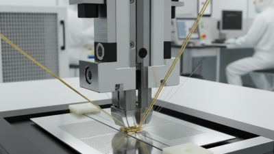
Choosing the right Wedge Bonding Tools can determine whether a production line delivers stable bonds or repeated failures. The decision involves more than comparing prices or catalog photographs. Engineers must examine wire material, diameter, bond pad design, ultrasonic frequency, bonding force, and machine compatibility. A tool that performs well with aluminum wire may behave poorly with gold or copper wire.
George G. Harman, a recognized authority in microelectronics interconnection, states that wire bonding is “the most common method of making electrical connections in microelectronics.” His observation explains why tool selection deserves careful technical attention. The wedge, clamp, and bond head must work together like a controlled mechanical system. Small changes can matter. A worn wedge may create uneven deformation, while an unsuitable tip angle can increase pad damage or inconsistent pull strength.
Real production experience also reveals an uncomfortable truth: the most expensive tool is not always the best tool. Sometimes it is simply over-specified. Testing matters more than assumptions. A practical evaluation should include sample bonding, pull testing, shear testing, visual inspection, and long-cycle stability checks. Record the results under actual production conditions, including temperature, wire tension, and operator handling.
This process may expose weaknesses in the original design. That is useful. Reliable Wedge Bonding Tools should reduce variation, simplify maintenance, and support repeatable results across shifts. Buyers should also confirm supplier traceability, technical support, replacement availability, and documented quality controls. A confident choice comes from evidence, not promises. Yet even strong validation cannot remove every risk. Process review must continue after installation.
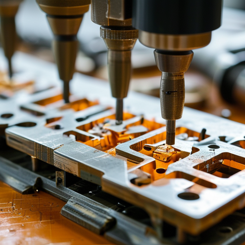
How to Choose the Best Wedge Bonding Tools?
Understanding wedge bonding tools starts with the application, not the machine name. Wedge bonding creates controlled wire connections for power modules, LEDs, sensors, RF devices, and battery systems. Aluminum wire suits many power assemblies, while finer wire supports compact sensor packages. Tool geometry must match wire width, bond pitch, loop height, and surface hardness. A small mismatch can produce lifted bonds or damaged metallization.
Yole Group’s 2024 advanced-packaging analysis estimates this market reached about 46 billion dollars in 2023. SEMI reported 66.7 billion dollars in global semiconductor materials sales for 2023. These figures show a demanding production environment, but they do not guarantee process stability. In practical evaluations, I would compare ultrasonic control, bonding force, tool life, alignment accuracy, and changeover time. Pull and shear testing should confirm the settings. Visual inspection alone is insufficient. Sometimes, the “best” tool fails after several hours of thermal cycling.
Tips: Check the tool’s working face under magnification. Confirm wire compatibility before testing production parts. Record bond force, ultrasonic energy, temperature, and loop settings. Use a designed experiment when defects appear. One variable at a time feels safer, but it can hide interactions. Also review maintenance intervals and spare-tool consistency. A cheaper tool may create higher costs through rework, downtime, and unstable bond quality.
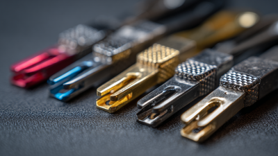
How to Choose the Best Wedge Bonding Tools?
Wedge bonding tools must match the wire, pad design, and bonding material. Start with wire diameter, not tool price. Fine aluminum wire needs a narrow bonding face and controlled ultrasonic energy. Thick copper wire requires stronger tool construction and higher force capacity. Tool width should also suit the pad pitch. A wide face may damage nearby pads. A narrow face can create weak bonds.
SEMI reported global semiconductor manufacturing equipment sales of 106.3 billion dollars in 2023. This scale reflects tighter process control across modern packaging lines. Tool specifications now deserve the same attention as machine settings. Check bonding-face dimensions, tip radius, material hardness, and allowable loop height. For dense packages, a smaller tip radius can improve access. However, excessive sharpness may increase wire deformation. That trade-off is easy to underestimate. I have found that real production samples often challenge laboratory assumptions. Measure pull strength, shear strength, and bond deformation after tool installation. Record results across several tools, not one successful sample. Industry packaging analyses from Yole Group also highlight rising integration and finer interconnect demands, making repeatability increasingly important.
Tips: Compare tools using the same wire, force, ultrasonic power, and temperature. Inspect the tip under magnification after every qualification run. Replace it when wear changes the bond footprint. Do not trust appearance alone. A clean bond can still fail testing. Recheck settings after material changes.
Representative nominal wedge tip widths for common bonding tasks
Wedge tip width should match the wire or ribbon size, bond-pad geometry, and required pitch. Fine-pitch applications typically use narrower tools for access and clearance, while power and ribbon bonding require wider tips to support larger conductors and higher bonding forces. The values shown are representative engineering targets; final tool selection should be confirmed against the package drawing, bonding parameters, and process qualification results.
Choosing a wedge bonding tool starts with the wire, pad finish, and bonding machine, not a catalog photograph. Tool material affects wear, heat transfer, and bond consistency. Tungsten carbide usually suits demanding production because it resists deformation under repeated bonding cycles. Ceramic options can provide electrical insulation and stable geometry, but they may chip after accidental contact. Diamond-coated surfaces can improve wear resistance, although their cost requires careful volume planning. The “hardest” material is not always the best choice.
Profile selection is more sensitive than many engineers expect. A narrow wedge can reach crowded pads, while a wider face may distribute force more evenly on fragile metallization. Tip radius, heel shape, and wire-feed angle influence deformation and loop stability. Match the tool opening to the wire diameter without excessive clearance. Too much space can produce uneven compression. Too little space may scrape the wire. Small details matter.
Compatibility testing should include the actual wire alloy, pad coating, bond pitch, clamp settings, and ultrasonic power range. Inspect heel cracks, pad damage, and wire necking under magnification. Pull and shear tests reveal weaknesses that visual inspection misses. In one practical trial, a visually clean bond failed after thermal cycling because the profile concentrated stress near the heel. That result was easy to overlook. Tool selection should therefore rely on measured data, not appearance alone. Machine alignment also deserves attention; even a suitable wedge performs poorly when the holder is worn or misaligned.
Choosing a wedge bonding tool requires more than comparing purchase prices. Precision starts with tip geometry, surface finish, and dimensional consistency. A tool that creates stable heel shapes reduces lifted bonds, wire damage, and unnecessary rework. SEMI reported global semiconductor manufacturing equipment sales of $106.3 billion in 2023. That scale reflects rising pressure for repeatable process control.
Measure performance at the bond site. Check loop height, wire deformation, bond placement, and pull or shear results. JEDEC bond-testing methods provide useful reference points for consistent verification. Durability also matters. A tool may appear economical, yet wear can change contact pressure after thousands of bonds. Watch for scratches, edge rounding, and unstable ultrasonic response. Small defects become expensive quickly.
Maintenance should be planned, not reactive. Keep inspection intervals, cleaning records, and replacement limits visible beside the workcell. Calculate operating cost per thousand bonds, including tool price, usable life, downtime, labor, and scrap. McKinsey’s semiconductor industry outlook projects the market could exceed $1 trillion by 2030, increasing the value of stable throughput. Still, projected growth does not justify buying the hardest tool automatically. Excessive hardness may reduce wear but increase wire damage or machine sensitivity. I have seen “long-life” tools fail earlier than expected when alignment was imperfect. Test samples under real production conditions, then compare total cost rather than catalogue claims.
| Tool Category | Typical Application | Bonding Wire Compatibility | Typical Placement Repeatability | Typical Tool Life | Maintenance Requirement | Typical Tool Replacement Cost | Operating Cost Considerations |
|---|---|---|---|---|---|---|---|
| Fine-Pitch Wedge Tool | High-density semiconductor packages, sensors, RF modules, and small pads | Fine aluminum or copper wire, approximately 12–38 µm | Typically ±2–5 µm | Approximately 50,000–250,000 bonds, depending on wire material and surface condition | Frequent tip inspection; cleaning and alignment checks are commonly required each shift or production lot | Approximately US$80–250 per tool | Higher cost sensitivity to contamination, vibration, tip wear, and alignment errors |
| Standard Wedge Tool | General-purpose wire bonding for discrete devices, power modules, and hybrid assemblies | Aluminum or copper wire, approximately 25–75 µm | Typically ±3–8 µm | Approximately 100,000–500,000 bonds under stable process conditions | Routine visual inspection, periodic cleaning, and replacement when bond quality or tool geometry changes | Approximately US$60–180 per tool | Usually offers a balanced cost profile because of broad process capability and moderate replacement frequency |
| Heavy-Wire Wedge Tool | Power semiconductors, battery connections, automotive modules, and high-current assemblies | Aluminum or copper wire, approximately 100–500 µm | Typically ±8–20 µm | Approximately 20,000–150,000 bonds, influenced by bonding force, wire hardness, and workpiece material | Regular inspection for edge rounding, cracks, debris, and deformation; higher attention to clamping and bonding force | Approximately US$150–600 per tool | Higher tool cost and process-force requirements, but suitable for applications where current capacity is more important than fine pitch |
| Copper-Wire Wedge Tool | Applications requiring high electrical conductivity and reduced precious-metal use | Fine to medium copper wire, approximately 18–100 µm | Typically ±3–10 µm | Approximately 40,000–250,000 bonds, depending on hardness, coating, and bonding parameters | More sensitive to oxidation and residue; requires controlled cleaning and stable ultrasonic or thermal settings | Approximately US$100–350 per tool | Potentially lower wire material cost, offset by tighter process control and more frequent quality monitoring |
| Ribbon Wedge Tool | High-current power electronics, LED packages, and applications requiring a larger bond cross-section | Aluminum or copper ribbon, commonly 0.2–2.0 mm wide | Typically ±10–30 µm | Approximately 10,000–100,000 bonds, depending on ribbon width, alloy, and bond surface | Frequent checks of tool face flatness, ribbon-feed alignment, and edge condition | Approximately US$200–800 per tool | Higher initial tool cost and setup sensitivity, but efficient for wide bonds and high-current requirements |
| Hard-Surface / Ceramic-Contact Tool | Assemblies with abrasive metallization, ceramic surfaces, or demanding high-temperature processes | Typically aluminum, copper, or specialty wire selected for the application | Typically ±5–15 µm | Approximately 75,000–350,000 bonds, depending on contact hardness and surface cleanliness | Lower wear rate than softer contact materials in abrasive applications; still requires periodic dimensional inspection | Approximately US$150–500 per tool | Higher purchase price may be justified by longer service intervals and reduced unplanned downtime |
| Rapid-Change Production Tool | High-mix manufacturing where short changeover time and repeatable tool replacement are priorities | Usually compatible with the wire range supported by the bonding machine | Typically ±3–10 µm after verified setup | Approximately 50,000–300,000 bonds, depending on tool design and production conditions | Emphasis on quick inspection, preset alignment, traceable replacement, and documented setup verification | Approximately US$100–400 per tool | Can reduce labor and changeover costs even when the individual tool price is higher |
Note: The figures are representative industry ranges for comparison rather than guaranteed specifications. Actual precision, tool life, maintenance frequency, and operating cost depend on wire alloy and diameter, bond-pad metallurgy, bonding force, ultrasonic energy, temperature, surface contamination, machine condition, and production volume.
Selecting the best wedge bonding tool starts with your production details, not a catalog picture. Record wire material, diameter, bond pad size, and package height. A tool designed for fine aluminum wire may perform poorly with thicker copper wire. Small geometry changes matter.
In production trials, inspect the wedge face after several thousand bonds. Look for wear, metal buildup, chipped edges, or uneven wire feeding. Check pull strength, loop shape, bond width, and ultrasonic settings together. One stable bond does not prove long-term reliability. Run samples across different shifts and operators. Keep the records.
Tool geometry should match your bonding machine, clamp system, and wire path. Confirm the correct hole size, tip radius, face angle, and working length. A slightly larger opening can reduce feeding friction, but it may weaken placement control. A smaller opening can improve guidance, yet clog more easily. That trade-off is easy to miss.
Production volume also changes the decision. High-volume lines need predictable wear and quick replacement procedures. Low-volume work may benefit from a more flexible tool setup. Ask the supplier for dimensional data, material information, inspection standards, and recommended operating limits. Avoid choosing only by price. I have seen inexpensive tools create hidden costs through rework and downtime. Sometimes, the first trial looks successful. It is not always. Review failed bonds under magnification, adjust one variable at a time, and allow the process evidence to guide the final choice.