
Leave Your Message

2026 Best Wire Guides and Ribbon Guides for Wire Bonders?

In 2026, choosing Wire Guides and Ribbon Guides for Wire Bonders means looking beyond basic dimensions. These small components help direct bonding wire or ribbon through a defined path. Their fit can affect feed consistency, placement, and wear around the bonding area. A guide that looks suitable on a catalog page may still perform poorly on a specific machine.

This overview introduces practical points for comparing guide options, including material, geometry, surface finish, compatibility, and maintenance needs. Equipment models, wire sizes, ribbon profiles, and process conditions all matter. Check manufacturer specifications and confirm critical dimensions before ordering. A polished finish can help reduce friction, but it cannot compensate for incorrect alignment. Small details count.

There is no universal “best” guide for every bonder. That is worth remembering. A choice that works well in one production line may require adjustment in another, especially when changing wire diameter or ribbon width. This guide aims to support informed evaluation, not promise identical results across setups. It also highlights questions buyers can ask suppliers, such as how tolerances are measured and which inspection records are available. In practice, careful testing on the intended equipment remains essential. Even a clear comparison has limits, and some selection decisions are less straightforward than they first appear.
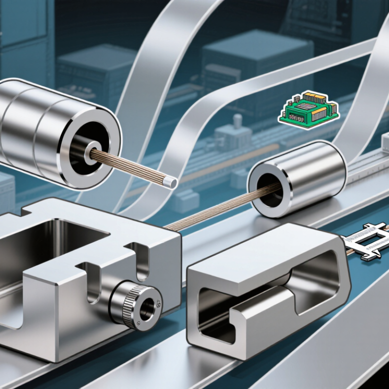
2026 Best Wire Guides and Ribbon Guides for Wire Bonders?

What Wire and Ribbon Guides Do in a Wire Bonder

In a wire bonder, a wire guide controls the path from the spool toward the bonding tool. It helps keep the fine wire centered and reduces snags, loops, and unwanted contact with nearby parts. The guide does not make the bond by itself. Its value is steadier delivery, so the bonding tool can place the wire where the process requires.

Ribbon guides perform a similar task, but ribbon is flat and directional. A guide must preserve its orientation and support the ribbon without pinching its edges. Even a small twist can change how the ribbon meets the work surface. The right guide depends on ribbon width, thickness, material, and the bonder’s feed arrangement. Wire and ribbon guides are not automatically interchangeable.

Fit matters. A passage that is too tight may increase drag or mark the material; one that is too loose may allow wandering. Operators can check for debris, burrs, wear, and smooth material movement during setup. A clean guide helps, but it cannot correct poor tension or misalignment elsewhere in the feed path. It is easy to blame the guide first. That may be wrong. Actual results depend on the machine, material, and process settings, so guide selection should be verified against equipment specifications and observed feed behavior.

How Wire Guides Differ from Ribbon Guides

A wire guide and a ribbon guide may look similar, but they control different shapes. Round wire needs a smooth, centered path through a small opening. A ribbon guide must keep a flat conductor aligned without twisting its broad face or scraping its edges.

For example, a 50 μm-wide ribbon needs a slot that controls lateral movement as well as height; a round wire needs concentric clearance. These are illustrative dimensions, not universal specifications. Check under magnification. Burrs, residue, or a slightly misaligned slot can change the feed path and produce inconsistent bonding.

The distinction matters as packaging processes diversify. SEMI reported that global assembly and packaging materials sales reached $25.3 billion in 2023, reflecting the scale of this production ecosystem. That figure does not prescribe guide geometry, but it shows why repeatable material handling matters.

A wire guide is usually judged by centering, friction, and smooth feed. A ribbon guide also needs to preserve ribbon orientation and avoid edge damage. Small changes matter. A wider slot may reduce rubbing, yet allow ribbon rotation; a tighter one may hold alignment but raise drag. The right clearance depends on ribbon thickness, width, surface condition, and bonder setup.

It is easy to overlook the guide itself when troubleshooting. Inspect the full feed path, not only the bond footprint.

SEM I, Global Semiconductor Materials Market Report, 2024.

Materials and Design Features That Affect Guide Performance

A wire guide looks simple, but its bore and surface finish can influence wire movement at every bond. Ceramic materials such as alumina offer hardness and wear resistance, while sapphire can provide a smooth contact surface. Neither material is automatically best. The choice depends on wire diameter, bonding speed, and how often the guide is replaced. Small scratches matter. A rough edge may snag fine wire or leave debris near the bonding area.

For ribbon wire, the opening needs to control the flat profile without pinching its edges. Rounded transitions can reduce friction as the ribbon passes through, while an overly loose channel may allow twisting. Dimensions should be checked against the actual wire, not just a drawing. A few microns can change how the ribbon tracks. That detail is easy to overlook.

Design also includes mounting and inspection. A guide that sits slightly off-axis can create uneven contact, even when its bore is well made. Under magnification, look for chips, residue, and wear at the entrance and exit. Keep notes on guide changes and wire breaks; patterns may reveal a fit problem. I would not assume a polished surface solves everything. Alignment and cleanliness can matter just as much.

How to Choose a Guide for Your Bonder and Bonding Application

Choosing a wire or ribbon guide begins with the bond, not the machine catalogue. Match the guide opening to the conductor’s width, thickness, and material. A round-wire guide must center the wire without scraping it; a ribbon guide needs enough clearance to prevent edge catching. Too much clearance can invite unstable feeding. Small differences matter.

Check the full path from spool to bonding tool. Look for sharp bends, burrs, residue, and alignment changes under operating tension. Then test with the actual wire, ribbon, loop height, and bond-pad layout.

SEMI’s 2024 World Fab Forecast projected global semiconductor capacity above 30 million 8-inch-equivalent wafers per month in 2024.

That scale makes repeatable feeding valuable, but it does not define the right guide for your process. Your setup does.

JEDEC JESD22-B116 provides a standardized wire-bond shear test, useful for assessing bond integrity after process trials. It does not certify a guide by itself. Record feed interruptions, wire deformation, bond consistency, and guide wear across repeated runs. Check again after cleaning; a guide can look fine and still behave differently.

I would not choose by nominal dimensions alone. That shortcut is tempting. It can miss friction, orientation, and real-world variation between lots.
Test, inspect, adjust—and document what changed.

Wire and Ribbon Guide Options to Consider in 2026

Choosing wire and ribbon guides in 2026 starts with the material and the bonder’s feed path. A round wire needs a smooth, correctly sized passage that limits friction without pinching the wire. Ribbon needs a guide slot that keeps its flat face aligned through direction changes. Small details matter.

Ceramic guides can offer wear resistance, while polished metal options may suit setups where easy handling is important. The right choice depends on wire diameter, ribbon width, tool clearance, and the machine’s actual motion—not just a catalog measurement. Check the edges. A tiny burr can mark ribbon or disturb wire feed. Also inspect how the guide sits near the clamp and capillary; a guide that looks right on the bench may drag during a fast loop. That is easy to overlook.

Before changing a production setup, run sample bonds and watch the feed under normal speed. Look for snags, twist, inconsistent loops, and visible surface marks. Record the guide dimensions and material, then compare results across repeated runs. I would not treat a nominal fit as proof of compatibility. Even a small mismatch can show up only after the line warms up or the spool tension changes. Keep the decision tied to measured performance and the bonder manufacturer’s clearance specifications.